FOR ATTAIN IT ON BOARD APPLICATIONS
OVERVIEW
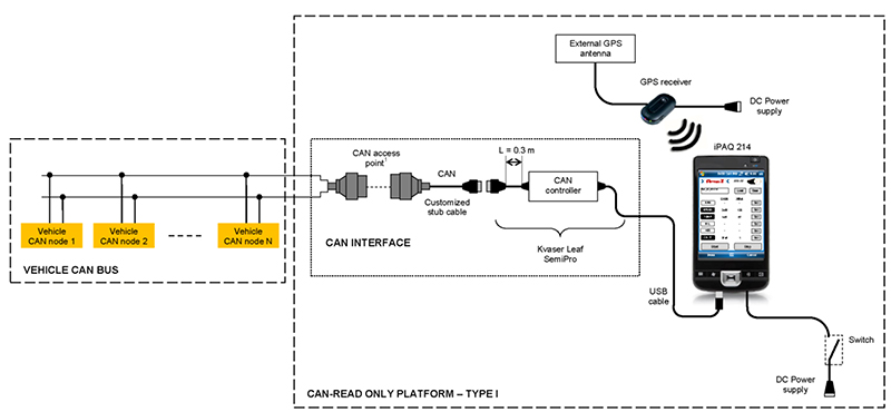
The CAN-Read Only Platform (Type I), for on board software applications developed by Attain IT, allows connecting to a vehicle CAN network, using an external CAN controller with an CAN-USB interface assuring data integrity of messages, thanks to using a read only method to access the network, for data analysis and on board real time processing.
HARDWARE COMPONENTS
The CAN-Read Only Platform (Type I) includes the following components:
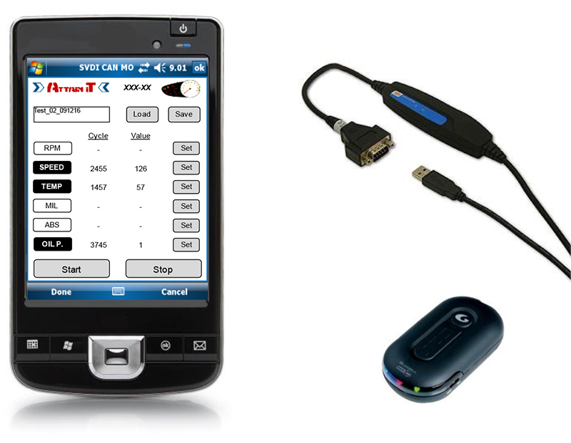
- 1 unit HP iPAQ 214
- 1 unit Kvaser Leaf SemiPro (external CAN controller)
- 1 unit GPS receiver
- 1 unit on board power supply for iPAQ (12-24 V.)
- 1 unit on board power supply for the GPS receiver (12-24 V.)
- 1 unit external GPS antenna (optional)
CAN CONTROLLER
The CAN controller is the Kvaser Leaf SemiPro which complies with ISO 11898-2 and allows interfacing the iPAQ-214 to the CAN network via USB.
The Kvaser Leaf SemiPro complies also with section 8.4.2.3.2, Physical media termination of ISO 15765-4:2005 (in particular it has not physical media termination) and can be assimilated to Type I ECU, with regards to the topology requirements as per section 5.2.2, Topology of SAE J1939-11.
The Kvaser Leaf SemiPro guarantees also galvanic isolation and the possibility to connect to CAN in silent mode. This feature assures no-writing access to the media while connected to the CAN bus, preventing the generation or the alteration of any message circulating across the network.
This silent feature is hardcoded in Attain IT software setup and can not be changed by the user.
The Kvaser Leaf SemiPro is CE marked and tested according to the following standards for electromagnetic compatibility:
- EN 55 022 1998 radiated
- EN 61 000-4-2 1995
- EN 61 000-4-3 1995-03
- EN 61 000-4-4 1995
- EN 61 000-4-6 1996
CONNECTION TO THE VEHICLE CAN NETWORK
The CAN connector on the external CAN controller (DSUB connector in attachment 2) shall be connected to the following vehicle side pins:
- CAN-L (CAN-Low) line
- CAN-H (CAN-High) line
- Signal ground
The cable between the DSUB connector and the CAN controller is 0.3 m, thus compatible with either of the following access points:
- OBD (On-Board Diagnostic) connector complying with sections 7.7.1, Diagnostic Connector and 7.7.4.2.1, Cable length, of ISO/PAS 27145-4:2006 (in particular maximum length between the OBD connector and the external test equipment equal to 5 m)
- OBD (On-Board Diagnostic) connector complying with SAE J1939-13 and section 5.2.2, Topology of SAE J1939-11 (in particular maximum cable stub length for the vehicle equal to 0.66 m and maximum cable length for the off-board diagnostic tool equal to 0.33 m).
- Directly to the CAN network, upon indication by the vehicle OEM following the requirements of either SAE J1939-11 (maximum cable stub length equal to 1 m) or to ISO 11898-2:2003 (maximum cable stub length equal to 0.3 m).
- FMS connector following the prescriptions and requirements provided by the vehicle OEM and/or the FMS electronic unit manufacturer.
GPS RECEIVER
The GPS receiver is connected to the iPAQ 214 wireless via Bluetooth and may be connected to an optional external antenna.
WEIGHTS AND DIMENSIONS
iPAQ 214
Dimensions (H x W x D): 126 x 76 x 16 mm
Weight: 192 g
Kvaser Leaf SemiPro
Dimensions (H x W x D): 100 x 25 x 20 mm
Weight: 110 g
GPS receiver
Dimensions (H x W x D): 30 x 15 x 8 mm
Weight: 50 g
ATTACHMENTS
A. Scheme of System Physical Connections
B. Kvaser Leaf SemiPro
- Kvaser Leaf SemiPro Data Sheet
- Extract from Kvaser Leaf User Guide
C. iPAQ 214 Data Sheet